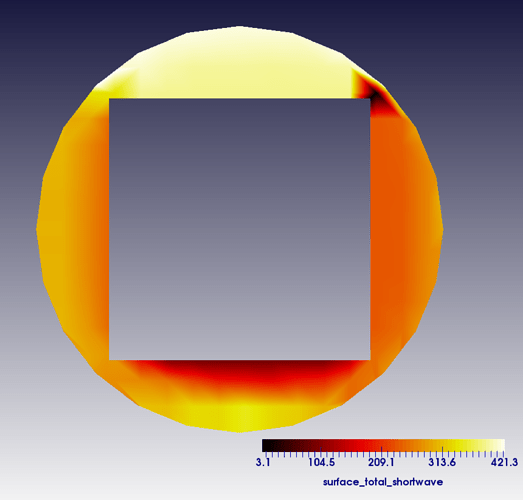
This is generally not wrong, though it is sometimes not so easy to describe how exactly this should work. By contrast, the case above where only the boundary was subject to the polar manifold, only mid points along the boundary would be placed along the curved description, whereas mid points in the interior would be computed by suitable averages of the surrounding points in the Cartesian coordinate system (see the manifold module for more details).Īt this point, one might assume that curved volume descriptions are the way to go. Whenever the triangulation requests a new point, e.g., the mid point of the edges or the cells when it refines a cell into four children, it will place them along the respective mid points in the polar coordinate system. In this last (optimal) case, which is also the default produced by GridGenerator::hyper_shell(), the curved manifold description (in this case a polar manifold description) is applied not only to the boundary faces, but to the whole domain. If we start with an initial mesh of 10 cells and refine the mesh three times globally without attaching any manifolds, we would obtain the following mesh: To give an example, consider the following situation of a two-dimensional annulus (with pictures taken from the manifold module). Within deal.II, the placement of new points during mesh refinement or for the definition of higher order mappings is controlled by manifold objects, see the manifold module for details. The step-54 tutorial program shows how to overcome this limitation by using CAD surfaces in terms of the OpenCASCADE library, and step-53 by providing the same kind of information programmatically from within the source code. This becomes problematic once the mesh is refined within deal.II and additional points need to be placed. A fundamental limitation of externally generated meshes is that the information provided by the generated cells in the mesh only consists of the position of the vertices and their connectivity, without the context of the underlying geometry that used to be available in the mesh generator that originally created this mesh. Besides the basic meshing capabilities collected in the GridGenerator namespace, deal.II also comes with interfaces to read in meshes generated by (quad- and hex-only) mesh generators using the functions of namespace GridIn, as for example demonstrated in step-5. Given a base mesh, deal.II is then able to create a finer mesh by subdividing the cells into children, either uniformly or only in selected parts of the computational domain. In the step-1, step-49, and step-53 tutorial programs, some techniques to generate grids available within the deal.II library have been introduced.

In many applications, the finite element mesh must be able to represent a relatively complex geometry.

This tutorial program presents an advanced manifold class, TransfiniteInterpolationManifold, and how to work around its main disadvantage, the relatively high cost. This program was contributed by Martin Kronbichler.


 0 kommentar(er)
